W6-7: Case Iterations
Cases
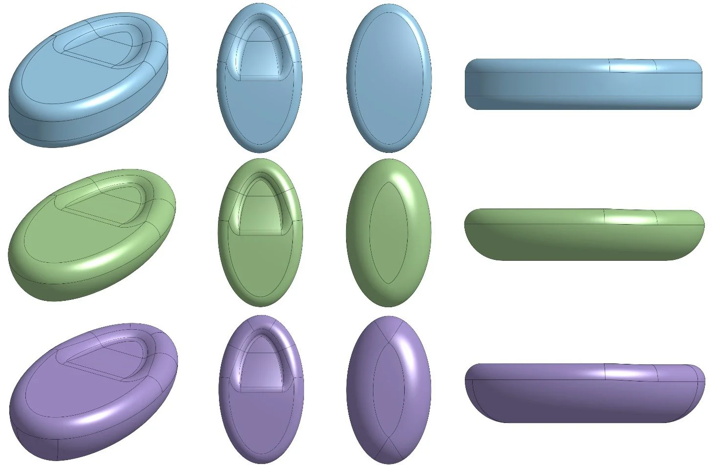
In the last post, I had just started on a concept for the handheld case. Since then, the overall shape has been refined twice.
V1: Blue (seen in previous post)
V2: Green
V3: Purple
Changes
V1 —> V2
Rounded the bottom half more to fit in the hand better
Narrowed the thumb indentation
V2 —> V3
Increased height to accommodate more rounding on the bottom half
A print of V3 was sent to California for Lisa Jellison’s review. Overall, she’s very happy with the shape. She recently purchased a device similar to what I’m working on making called Dharma Dr Tabs to see how she liked them in comparison to the TheraTapper.
Lisa was quite impressed with these tabs, but she said that she likes the feel of the V3 case significantly more, since it sits in the full hand rather than just held between three fingers. This was my exact thought process when making my design. The thumb indentation that the tabs have was an interesting idea, similar to a worry stone, but they didn’t look very satisfying to hold. So, I kept the thumb indentation and then made them larger and longer to fully fit in the hand. Lisa is very excited to see the finished prototype now after holding the concept print.
Case Interior
Now that I had a shape that I was happy with, I moved onto hollowing it out and figuring out where to put things. Before getting too deep into component placement, I wanted to test if a new motor would work well in this case. So, similarly to the first test print of this project where I made a small box that held the disc motor, I put brackets in the middle of V3 to hold a motor in place for testing.
Two attempts were made for this test due to a prong in the first print breaking immediately. The second print had prongs that were too thick, but it turned out that the motor is encased in silicone, so it was still possible to get it seated for testing. It seemed just as good as the disc motor while being a little quieter, so that made the decision easy for which type of motor to use.
Now onto actually putting things where they need to go.
Since the previous post, I have changed the main board from a ThingPlus ESP32C6 to a Seeed Studio XIAO ESP32C6. Same wireless capability, but significantly smaller. The only downside is that the Seeed doesn’t have a battery fuel gauge built into it like the ThingPlus does. I’ll come back to that later.
With that in mind, here is the current interior layout of the case body and lid.


At the moment, there is nothing to hold down the Seeed, but that will come later because it turns out that I need to make a custom PCB again after all, so I’m not getting too in-depth around the boards yet until I know what I’m fully working with.
I don’t like the placement of the motor at the moment, because all of the vibration is concentrated at the fingertips. I could just flip everything around, but having the USB port by the fingertips doesn’t feel as nice. So, I’m going to mess around with swapping the motor and the battery so that the motor is centralized. The battery will need to be on a riser like the board is so that it can fit width-wise, but that shouldn’t be a problem.
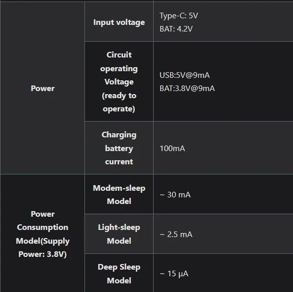
A bigger problem is battery capacity. Seeed Studios did not make the power consumption for this board particularly clear.
9mA circuit operating voltage on battery power, but 30mA in modem-sleep seems…odd. Unless they meant 3.0, in which case that would make a lot more sense. I have submitted a ticket to Seeed Studio to ask them about it directly.
Going off of 30mA for a worst-case scenario for power draw and 90mA for the motor brings it to 120mA for one hour. Smaller than I expected, but I won’t complain. I can offer more than the 1.5 hours of battery life I promised in the project proposal - yay!
The battery used for the model at the moment is 270mAh, which would provide approx. 2.25 hours of use (worst case) or approx. 2.75 hours (if 30mA is supposed to be 3.0). I’ve been going back and forth on whether or not to jump up to something that’s more like 400mAh so that charging doesn’t have to be as frequent, but that would also make fitting the battery into the case more difficult. I’ve ordered both the 270 and 400 for the time being, but I think I’m going to aim to stick with the 270.
PCBs
Turns out that I’m going to need to make a custom PCB after all. In using LEDs for testing thus far, I forgot that it’s not a great idea to wire a DC motor to a pin directly, and only stumbled over a reminder about that in battery research. Oops. Good news is that it needs half of the circuit I used for Return to Center, since it’s only controlling one motor. Bad news: if I want to have a fuel gauge on the battery, I either need to have a separate breakout board for that, or I need to put one into this new PCB. I’m planning to attempt the latter. I also keep forgetting that I’d probably be best off having a PCB for the control box as well. It might not be as necessary, but it would be a cleaner design and I need to put a fuel gauge on that battery anyway. PCBs will be this weekend’s project.
Two Weeks Left
In writing the timeline of this project, I set the goal of being done with the final prototype by November 1st. The steps I still need to do are as follows:
Handheld PCB design + fuel gauge integration
Control box PCB design + fuel gauge integration
Handheld case refinement
Keeping the boards in place
Cap closure
Probably will be a snap joint, still need to look into this more
Control box case
Really just needs to be a box, nothing fancy. Shouldn’t take very long. Will depend on its respective PCB though.
If I can get the PCBs both designed and ordered by Sunday night, I think it might still be doable. Worst case, I’m anticipating going about 1 week over.


